Abstract : A collector-type electromagnetic flowmeter is widely used in downhole flow measurement and other special occasions. The finite element software ansys is used to establish a magnetic field simulation model of this type of collector-type electromagnetic flowmeter, and this kind of current-collecting electromagnetic is established. A magnetic field simulation model in which a fluid in a flow meter contains a granular object with a high magnetic permeability.
Keywords: ansys, current collector type, electromagnetic flowmeter, simulation In recent years, the internal magnetic field division of the electromagnetic flowmeter has attracted the attention of researchers. Jin Ningde [1-2] et al. simulated the magnetic field distribution of an external-flow electromagnetic flowmeter. Zhao et al. and Li Bin et al. calculated the magnetic field distribution of an electromagnetic flow sensor saddle-shaped excitation coil [3]. Wang Jingzhuo The numerical value of the flow meter weight function is simulated and verified [4]. Qi Huifeng et al. used ANSYS to perform modeling research on the electromagnetic flow meter [5]. A collector-type electromagnetic flowmeter is widely used in oil downhole measurement and other special occasions because of its special construction. Due to the particularity of the collector-type electromagnetic flowmeter construction, the internal magnetic field division is more complex than that of the ordinary structure electromagnetic flowmeter. The study of the distribution of its internal magnetic field is of great significance to the design of the flowmeter. In this paper, ansys finite element software is used to model and simulate the magnetic field sensitive field inside the electromagnetic flowmeter. Under this model, the electromagnetic flowmeter is studied when adding some particles with different magnetic permeability in the electromagnetic flowmeter. Internal magnetic field distribution.
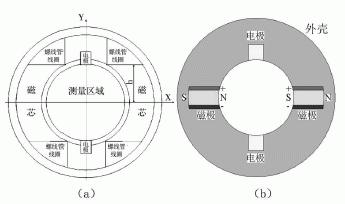
1 flow meter structure and magnetic field distribution simulation Collecting electromagnetic flowmeter is widely used in oil downhole measurement, which embedded two emission poles and two receiving electrodes in the flow meter housing. Since the umbrella collector is installed on the bottom of the electromagnetic sensor, when the flow meter is located at a specified measuring point, the current collector is opened to close the flow channel of the fluid between the casing and the logging tool, forcing the fluid to be completely or totally Most of the flow through the measurement area of ​​the electromagnetic sensor, and re-flow back to the wellbore through the outlet, the cross-sectional structure of the downhole manifold flowmeter shown in Figure 1 (a).
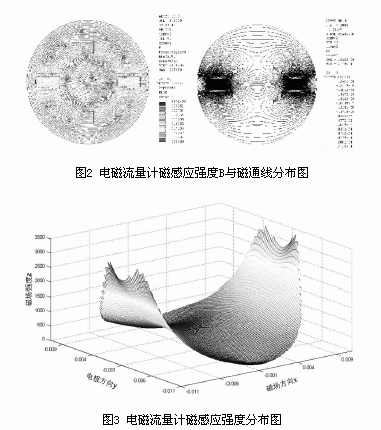
The magsolv command was used to solve the magnetic field distribution problem of the outflow electromagnetic flowmeter statically to obtain magnetic induction B distribution and 2D magnetic flux distribution, as shown in (a) and (b) of FIG. 2 , respectively. It can be seen that the distribution of the magnetic field in the sensor pipeline is relatively uniform, and the magnetic lines are dense near the surface area of ​​the magnetic pole, indicating that the measurement sensitivity of this part is high. In order to more clearly understand the distribution of the magnetic induction field inside the flowmeter, the magnetic induction intensity distribution field of the electromagnetic flowmeter measurement area is established. As shown in FIG. 3 , the magnetic induction intensity of each part can be clearly obtained from the simulated magnetic induction distribution map.
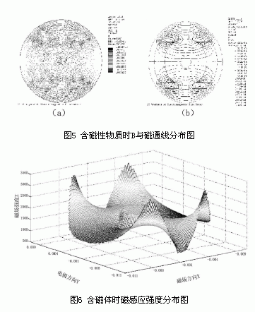
 The excitation current is applied to the coil, and the ANSize command is used to mesh the ANSYS model. The magsolv command is used to solve the magnetic field distribution problem of the magnetic flowmeter containing magnetic material statically, and the magnetic induction intensity B distribution and the 2D magnetic flux line are obtained. Distribution, as shown in (a) and (b) in Figure 5.
As can be seen from Figure 5, when the magnetic material flows through the measurement area of ​​the sensor tube, the magnetic field near the magnetic material changes, which in turn affects the overall distribution of the measured magnetic field. That is, the magnetic substance in the fluid also affects the measurement of the current collecting electromagnetic flowmeter. The numerical simulation results show that the distribution map shown in Figure 6, can be seen from the simulation results, the fluid contains magnetic material, this part of the magnetic induction intensity is increased, is affecting the entire space of the magnetic induction intensity distribution. 3 Conclusions Collective electromagnetic flowmeters have a wide range of applications in oil and gas wells measurement with a special structure. This paper establishes a simulation model for this special structure of flowmeters and uses a finite element method for the collection of electromagnetic flowmeters. The measurement was carried out by computer simulation, which laid a certain foundation for the simulation measurement of magnetic field and its structural optimization in the electromagnetic flowmeter simulation method using finite element method.
references:
[1] Jin Ningde, Zong Yanbo, Zhang Yuhui, et al. Numerical simulation of magnetic field distribution characteristics of four-electrode electromagnetic flowmeter[J]. Industrial Measurement,2009,19(2):2-6.
[2] Jin Ningde, Zong Yanbo, Zheng Guibo, et al. Analysis of measurement characteristics of electromagnetic flowmeter in polymer injection wells[J].Acta Petrolei Sinica,2009,30(2):308-311.
[3]ZHAO Yu, LI Bin, CHEN Wenjian. Calculation Method of Magnetic Field Distribution of Electromagnetic Flow Sensor Saddle-shaped Excitation Coil [J]. Journal of Shanghai University (Natural Science Edition), 2008, 14(1): 31-35.
[4]Wang Jingzhuo. Numerical simulation and verification of electromagnetic flowmeter weight function[J]. Chinese Journal of Scientific Instrument, 2009, 30(1): 132-137.
[5]Qi Huifeng, Yan Yi, Wu Hongxuan. Research on Modeling of Electromagnetic Flowmeter Based on ANSYS[J]. Journal of Instrumental Instrument, 2008,29(2):372-376
Keywords: ansys, current collector type, electromagnetic flowmeter, simulation In recent years, the internal magnetic field division of the electromagnetic flowmeter has attracted the attention of researchers. Jin Ningde [1-2] et al. simulated the magnetic field distribution of an external-flow electromagnetic flowmeter. Zhao et al. and Li Bin et al. calculated the magnetic field distribution of an electromagnetic flow sensor saddle-shaped excitation coil [3]. Wang Jingzhuo The numerical value of the flow meter weight function is simulated and verified [4]. Qi Huifeng et al. used ANSYS to perform modeling research on the electromagnetic flow meter [5]. A collector-type electromagnetic flowmeter is widely used in oil downhole measurement and other special occasions because of its special construction. Due to the particularity of the collector-type electromagnetic flowmeter construction, the internal magnetic field division is more complex than that of the ordinary structure electromagnetic flowmeter. The study of the distribution of its internal magnetic field is of great significance to the design of the flowmeter. In this paper, ansys finite element software is used to model and simulate the magnetic field sensitive field inside the electromagnetic flowmeter. Under this model, the electromagnetic flowmeter is studied when adding some particles with different magnetic permeability in the electromagnetic flowmeter. Internal magnetic field distribution.
1 flow meter structure and magnetic field distribution simulation Collecting electromagnetic flowmeter is widely used in oil downhole measurement, which embedded two emission poles and two receiving electrodes in the flow meter housing. Since the umbrella collector is installed on the bottom of the electromagnetic sensor, when the flow meter is located at a specified measuring point, the current collector is opened to close the flow channel of the fluid between the casing and the logging tool, forcing the fluid to be completely or totally Most of the flow through the measurement area of ​​the electromagnetic sensor, and re-flow back to the wellbore through the outlet, the cross-sectional structure of the downhole manifold flowmeter shown in Figure 1 (a).

Figure 1 electromagnetic flowmeter structure diagram
Current-collected electromagnetic flowmeter ANSYS simulation model shown in Figure 1 (b) below. In the figure, the electromagnetic flowmeter has two magnetic poles in the horizontal direction and two electrodes in the vertical direction. The magnetic pole is composed of a magnetic core and a coil, that is, a coil is wrapped on the outer side of each magnetic pole core to generate a cross. Change the magnetic field. In the simulation, the length of the magnetic core of the sensor is 8mm and the width is 4mm. The material is a magnetic core; the thickness of the coil wrapped around the core is 1mm; the material is copper wire; the length and width of the electrode are 4mm, and the material is stainless steel. After solenoid coil current is applied, the left magnetic pole is S pole and the inner is N pole; the right magnetic pole is N pole, and the inner pole is S pole. The magsolv command was used to solve the magnetic field distribution problem of the outflow electromagnetic flowmeter statically to obtain magnetic induction B distribution and 2D magnetic flux distribution, as shown in (a) and (b) of FIG. 2 , respectively. It can be seen that the distribution of the magnetic field in the sensor pipeline is relatively uniform, and the magnetic lines are dense near the surface area of ​​the magnetic pole, indicating that the measurement sensitivity of this part is high. In order to more clearly understand the distribution of the magnetic induction field inside the flowmeter, the magnetic induction intensity distribution field of the electromagnetic flowmeter measurement area is established. As shown in FIG. 3 , the magnetic induction intensity of each part can be clearly obtained from the simulated magnetic induction distribution map.

2Magnetic flowmeter magnetic field distribution simulation in the pipeline containing magnetic material
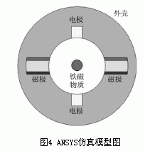
In order to examine the magnetic substances contained in the fluid, the influence of the magnetic field distribution of the electromagnetic flowmeter is shown in the model of ANSYS simulation model shown in FIG. 4 . In the figure, a diameter magnetic sphere is set in the measurement area of ​​the sensor pipe, and the relative magnetic permeability of the magnetic sphere is set as: μ=10. 
As can be seen from Figure 5, when the magnetic material flows through the measurement area of ​​the sensor tube, the magnetic field near the magnetic material changes, which in turn affects the overall distribution of the measured magnetic field. That is, the magnetic substance in the fluid also affects the measurement of the current collecting electromagnetic flowmeter. The numerical simulation results show that the distribution map shown in Figure 6, can be seen from the simulation results, the fluid contains magnetic material, this part of the magnetic induction intensity is increased, is affecting the entire space of the magnetic induction intensity distribution.

references:
[1] Jin Ningde, Zong Yanbo, Zhang Yuhui, et al. Numerical simulation of magnetic field distribution characteristics of four-electrode electromagnetic flowmeter[J]. Industrial Measurement,2009,19(2):2-6.
[2] Jin Ningde, Zong Yanbo, Zheng Guibo, et al. Analysis of measurement characteristics of electromagnetic flowmeter in polymer injection wells[J].Acta Petrolei Sinica,2009,30(2):308-311.
[3]ZHAO Yu, LI Bin, CHEN Wenjian. Calculation Method of Magnetic Field Distribution of Electromagnetic Flow Sensor Saddle-shaped Excitation Coil [J]. Journal of Shanghai University (Natural Science Edition), 2008, 14(1): 31-35.
[4]Wang Jingzhuo. Numerical simulation and verification of electromagnetic flowmeter weight function[J]. Chinese Journal of Scientific Instrument, 2009, 30(1): 132-137.
[5]Qi Huifeng, Yan Yi, Wu Hongxuan. Research on Modeling of Electromagnetic Flowmeter Based on ANSYS[J]. Journal of Instrumental Instrument, 2008,29(2):372-376
Robot has been used widely in modern industry. With the deeply urge for automation in grinding field, robot has been a smart mehtod to realize grinding automation. Our Force Control System connects with robot, can work in grinding polishing sanding, high working efficiency, low cost and cleaning working environment. More and more manufacturers choose this method to realize automation reform. So this method has been used in metal,plastics,acrylic, wood, compound material processing in 3c, household sanitary ware, auto parts, transportation tools etc.
sanding use robot, robot use in sanding, robotic sanding machine
DARU Technology (Suzhou) Co., Ltd. , https://www.darudfc.com
